The 21st Shenzhen International Machinery Manufacturing Industry Exhibition
Sep. 1 – 4, 2020 | Shenzhen · China
2020/07/20 10:00 | Pageview:1643 | From: Moldmaking Technology
While part quality and profits go hand-in-hand, high productivity (faster cycle times) alone can impair quality and reduce profits, if not performed correctly. The key is designing high-efficiency capabilities into the mold/molding system, which means computing precise shrinkage (at four decimal accuracy, e.g. 0.0275 inch/inch) and the accurate minimum cycle time (19.8 seconds) based on material, part geometry, required tolerances, filling and maximum-performance, computed cooling. Then monitoring this cycle time with sensor-based quality control to minimize part rejects.
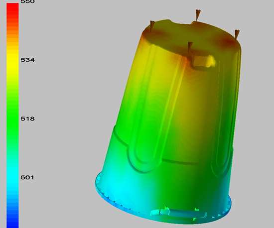
Isotherms of a HDPE container at the instant of cavity filling from the flow analysis. Filling conditions are:
Injection time: 2.9 sec with slowed finish; Melt temperature: 550°F; Mold surface temperature at equilibrium: 87°F
Expert analysis and optimization of the mold and molding process require intelligent, interactive management of all components of the mold/molding system before the first metal chip falls.
A mold builder can help achieve product quality by defining quality, functionality, dimensional/shape accuracy and appearance; starting with a robust product and mold design (resulting in a sufficiently wide moldability window), machine selection, and process design. Analysis, design and implementation of the critical quality pathway or CQP and adherence to the computed control limits of the material, molding cell, mold cooling, process, machine and quality control are vital.
CQP stands for uninterrupted movement of polymer molecules and additives (if any) from the barrel to the critical regions of the part to achieve the required part quality. Mold cooling computations, such as required size/shape, number and locations, edge-to-part and edge-to-edge distances of cooling passages using the approved, minimum cycle time and the planning of sensor-based quality control are key.
Expert analysis and optimization requires the following steps:
Send the questionnaire to the customer to determine the objectives of the analysis/optimizations.
Quote the project.
Request critical tolerances specs of the part and mold, molding machine parameters and five pounds of material with additives/colorant (if any) for flow (rheological and thermal) and precise shrinkage characterization.
Complete one or both of these experiments in the molding lab using a unique test mold and highly controlled molding conditions. Based on these experiments, fine-tune the three flow graphs (as well as the rheological and thermal parameters) of the resin and its shrinkage master curve.
Review part design for robustness and design for manufacturability (DFM).
Complete “what if” evaluations and finite element analysis (non-linear stress, transient thermal).
What If and FEA
Molding and testing specimens that have similar thicknesses as those of the product’s critical regions are important steps because thickness affects the strength/elongation/impact resistance of semi-crystalline polymers due to varying ratios of mostly amorphous skin and core of higher crystallinity.
Generally, the range of specimens falls between 0.05 inch for packaging parts and 0.40+ inch for pressure vessels. With this technique +/-1-5% computational accuracy was achieved in nonlinear buckling.
Complete an initial flow analysis to judge design feasibility.
Compute the attainable, long-term part tolerance control with four decimal accuracy.
Submit the computed, minimum possible cycle time to management for approval.
Compute shrinkage for the specified part dimensions to four-decimal accuracy. Also, include secondary crystallization-related, post-molding shrinkage upon request.
Compute cooling channel locations (edge-to-part and edge-to-edge distances at +/-0.020 inch accuracy) to guide the mold designer based on the approved minimum cycle time.
Perform precision flow analysis using 10 to 15 analysis runs to define the ‘sweet spot’ and robustness of mold filling.
Evaluate cold runners or hot runners for temperature conditions, pressure losses, shear rates, polymer residence time and effect on the precision of mold filling and packing/holding.
Evaluate gating for adequacy, shear rate, shear heat and pressure loss.
Complete precise warpage analysis, if requested.
Compute the robust process and evaluate the adequacy of machine parameters, such as clamping force, shot size, injection pressure, injection rate, min./max. residence time and plasticizing capacity.
Review mold design.
Complete/explain the analysis report.
Participate in mold trial runs, design of experiments (DOE) and for certain medical application initiate/maintain the design control document, if requested.


Organized by: Shenzhen Huanyue Convention & Exhibition Co., Ltd © All Rights Reserved.
Tel: +86-755-23940012
Email: info@simmtime.com
|
 Loading...